South Pole Telescope Design
| SPST342 | |||||
| SPST320 | |||||
| SPST313 | |||||
| SPST 307 | |||||
| SPST304 | |||||
| SPST298 | |||||
| SPST271 | |||||
| SPST208 | |||||
| SPST183 | |||||
| SPST148 | |||||
| SPST152 | |||||
SPST129
| |||||
| SPST67 |
SPST342
This is not so much an actual design as an exercise in what happens when the chopper is moved back from the image of the primary following the secondary, in order to give more clearance at the prime focus.
In this case, three models have been run: SPST342 has the chopper centered, and SPST343 and 344 have the chopper rotated by �2.2 degrees about the line that is the intersection between the chopper surface and the plane of symmetry of the telescope. In this model, this amount of chopper rotation displaces the central beam by �0.288 degrees. The full chopper throw, plus to minus, is therefore more than half the size of the array.
Note that in this model, the lens is plastic.

Figure 1 - side view, all fields.
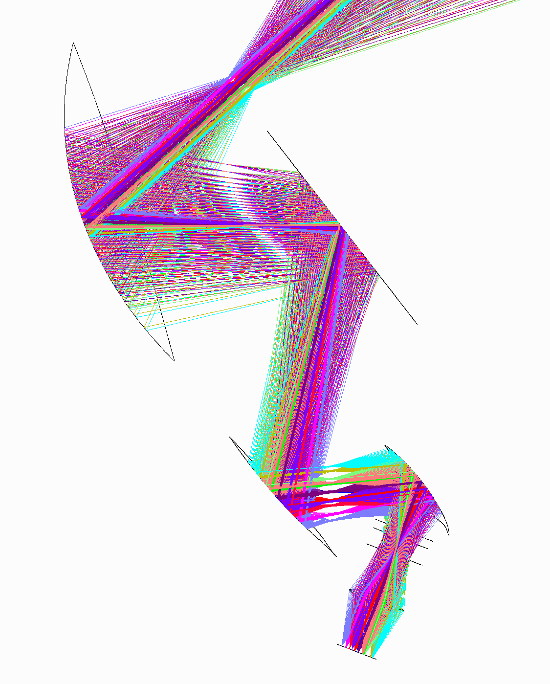
Figure 2 - detail of secondary, chopper, and detector. Note lens is plastic.

Figure 3 - Spot diagram, chopper centered
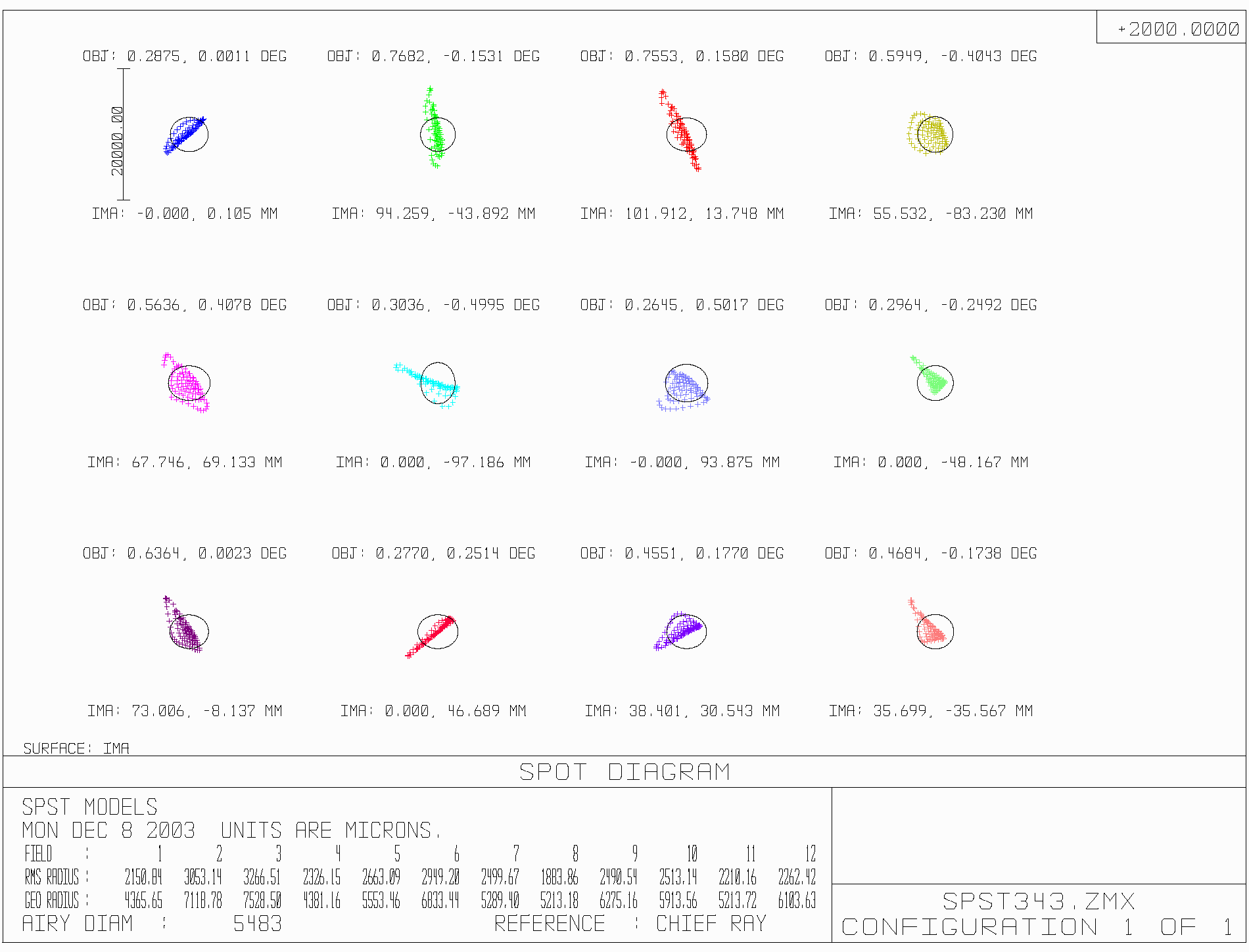
Figure 4 - chopper at +2.2 degrees. Note that the image positions are fixed and the object positions (in degrees on the sky) have changed.

Figure 5. - Chopper at -2.2 degrees.
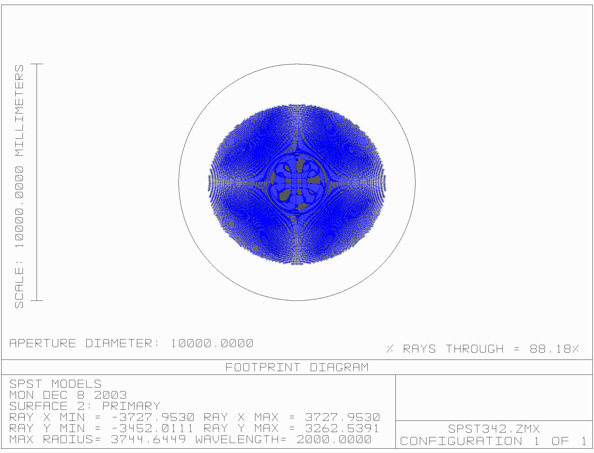
Figure 6 - footprint of central field on primary mirror, chopper centered.
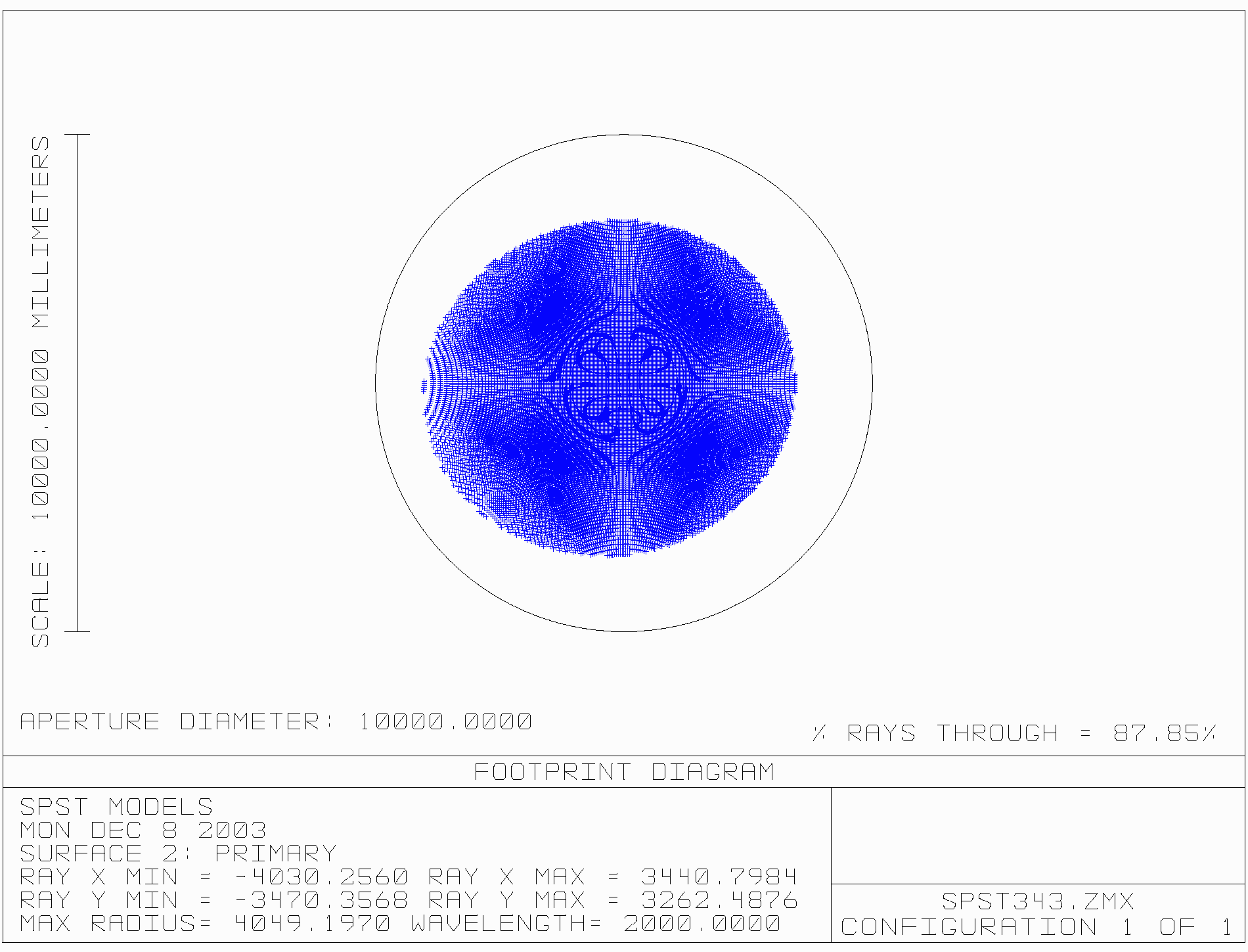
Figure 7 - footprint of central field on primary mirror, with chopper at +2.2 degrees. The corresponding diagram with the chopper at -2.2 degrees is a mirror image of this one. Note that the illumination patter has been displaced about 300 mm

Figure 8 - footprint of all fields on primary mirror, chopper centered.

Figure 9 - footprint of all fields on primary mirror, chopper at 2.2 degrees.

Figure 10 - footprint of all fields on primary mirror, chopper at -2.2 degrees.

Figure 11 - footprint of all fields on secondary mirror, chopper centered.
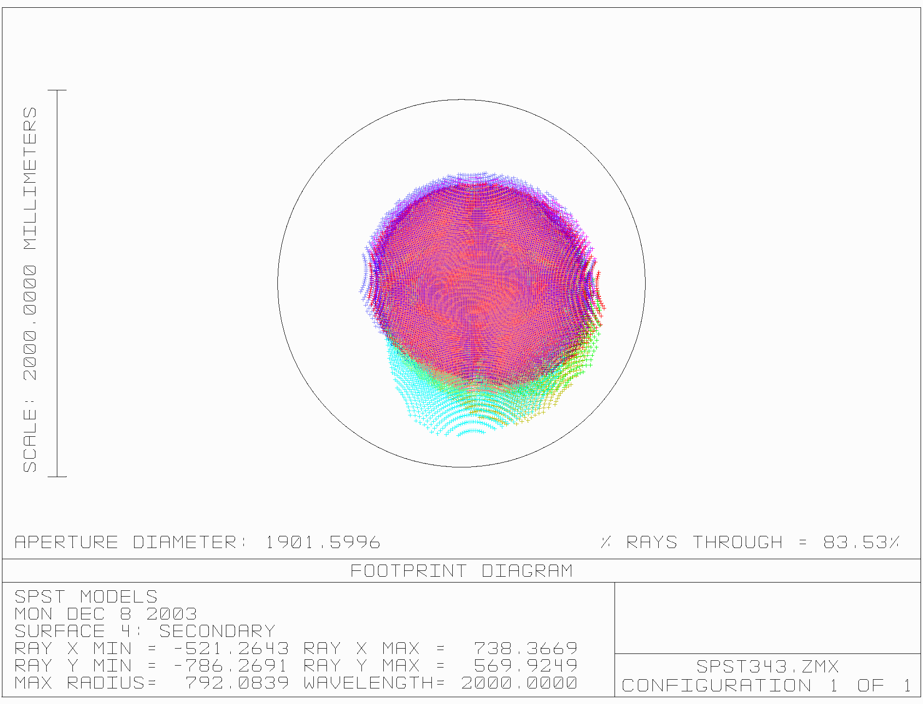
Figure 12 - footprint of all fields on secondary mirror, chopper at +2.2 degrees.
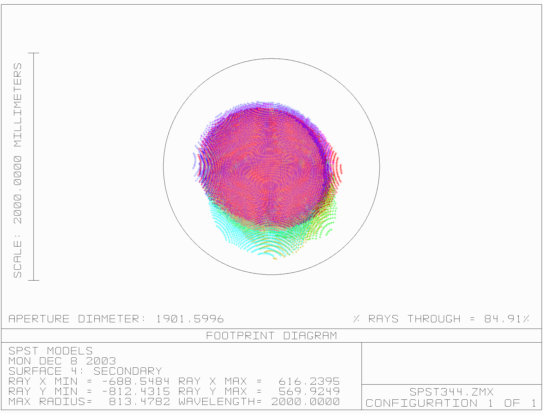
Figure 13 - footprint of all fields on secondary mirror, chopper at -2.2 degrees.