South Pole Telescope Design
| SPST342 | |||||
| SPST320 | |||||
| SPST313 | |||||
| SPST 307 | |||||
| SPST304 | |||||
| SPST298 | |||||
| SPST271 | |||||
| SPST208 | |||||
| SPST183 | |||||
| SPST148 | |||||
| SPST152 | |||||
SPST129
| |||||
| SPST67 |
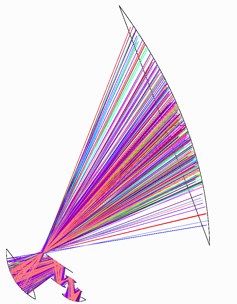
Figure 1 Side view, all fields. Note that only the last mirror is inside the dewar.
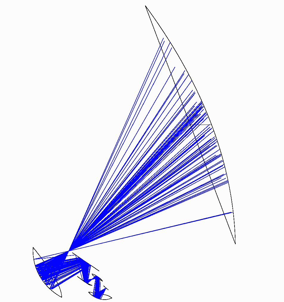
Figure 2 - Same as Fig.1, but only the center field is shown.
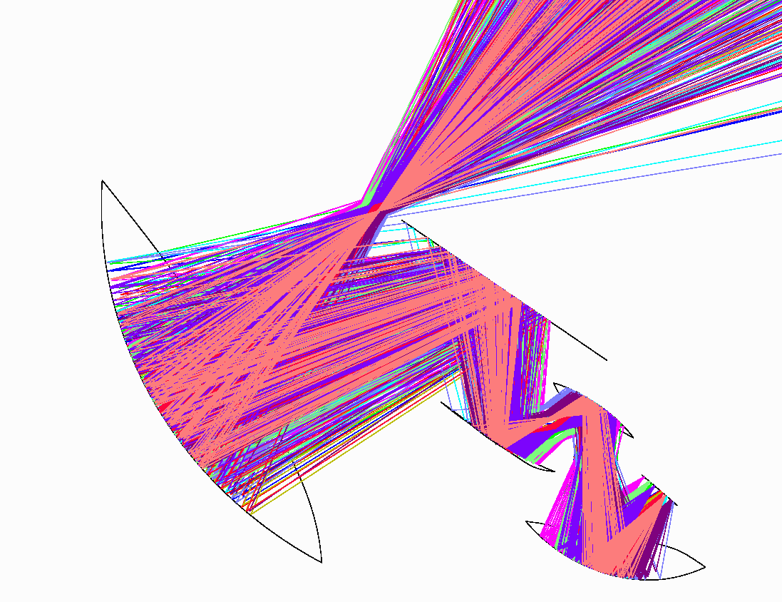
Figure 3 --- detail of Fig.1 How can the focal plane be shielded from the window? Where do the filters go?

Figure 4.---Detail of Figure 2
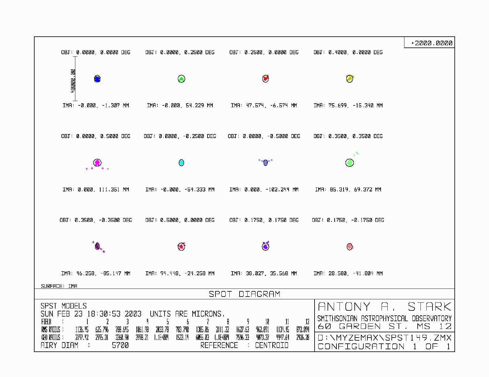
Figure 5. --- Spot diagram---acceptable at 2mm wavelength, but not shorter.
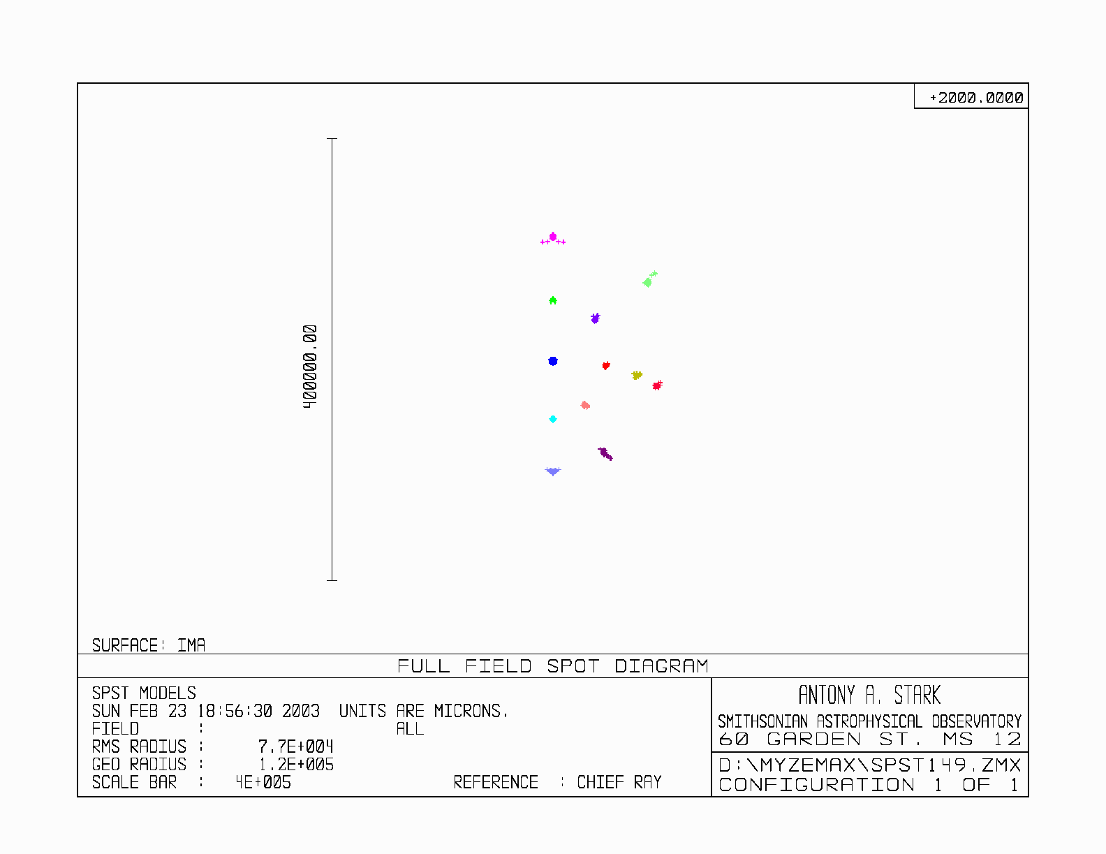
Figure 6. ---Full field spot diagram.
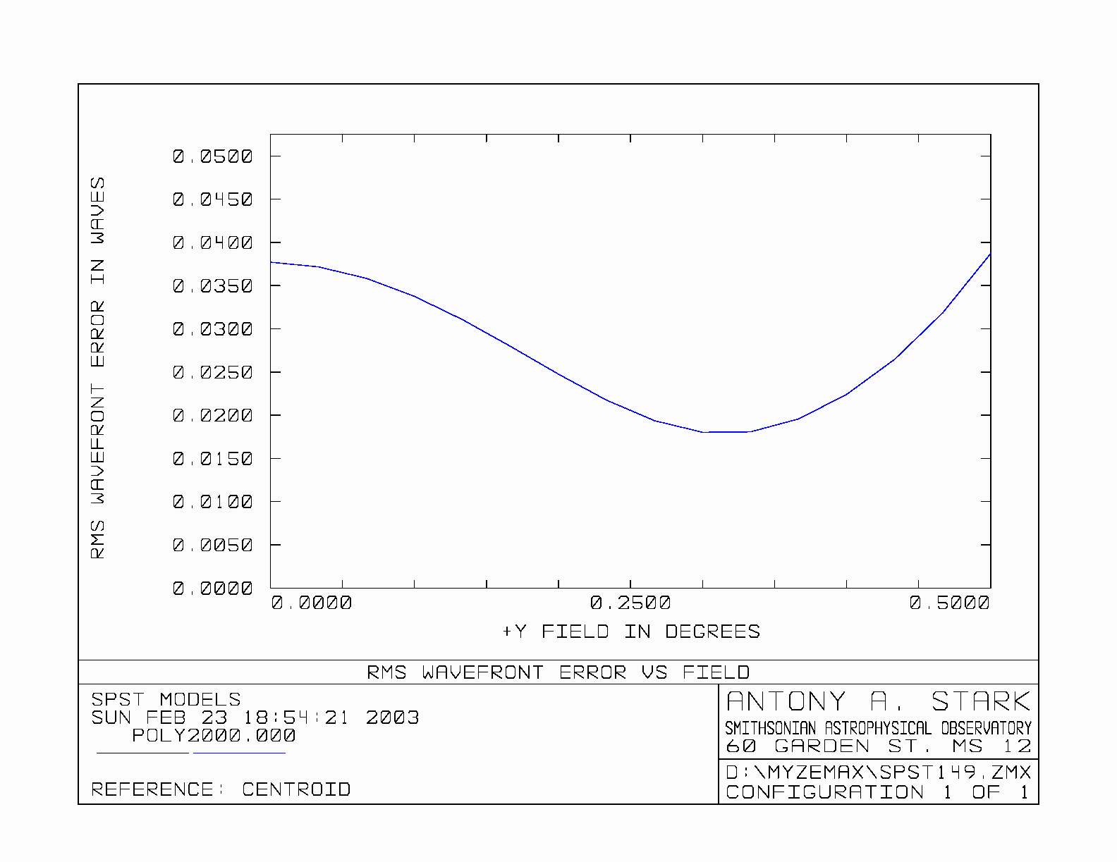
Figure 7.--- rms wavefront error vs. field. Wavelength is 2 mm.