Millimeter Optics
Artificial dielectric materials, such as expanded Teflon sheets, have long been used as impedance matching layers for millimeter and sub-millimeter vacuum windows, filters and lenses. More recently, there has been concentrated effort to design and produce micro-patterned artificial dielectric layers in silicon through deep-reactive ion etching. Micro- patterned layers, also known as metamaterials, are composed of a repeated structure on sub-wavelength scales and can be characterized by an effective dielectric constant. I have expanded upon the effective capacitance method of Biber [1] to study several simple patterned artificial dielectrics (squares, circles, crosses, grooves). I have also used this method of calculating effective dielectric constants to study and design tools to fabricate several different impedance tapers.
For each layer in a micro-patterned multi-layer impedance transformer, I calculate the dielectric constants in the long wavelength limit using the effective capacitance technique as numerically solved using a relaxtion method. I have also used frequency dependent simulations of effective dielectric constants in Ansys HFSS, and showed that in agreement with Biber, the effective capacitance method underestimates the effective dielectric constant. Using the transfer matrix method, I then compute the S-parameters of multi-layer micro-patterned impedance transformers. From this point, it is a simple procedure to design micro-patterned Chebyshev transformers. By inverting the relationship between pattern geometry and effective dielectric constant, I have also studied the prospect of custom-ground machine tools to achieve linear and Klopfenstein impedance tapers.
Using a slitting saw spindle I have designed, we are currently trying to machine a pyramidal taper into a brass disc, which can then be used to heat stamp an HDPE window, creating a pyramidal impedance taper in the surface. The sawing jig is shown below, with the first brass test piece.
[1]S. Biber et. al., "Design of artificial dielectrics for anti-reflection-coatings," 33rd European Microwave Conference Proceedings,Vol. 3, pp. 1115-1118, 2003
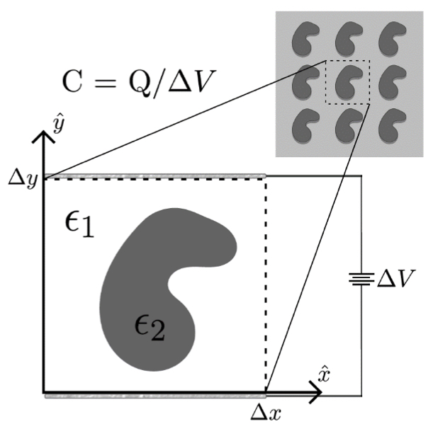
The setup of the canonical problem of estimating the effective dielectric constant of a micro-patterned structure through the calculation of the capacitance of a pattern unit cell. Boundary conditions determine the polarization for which the dielectric constant is being calculated.
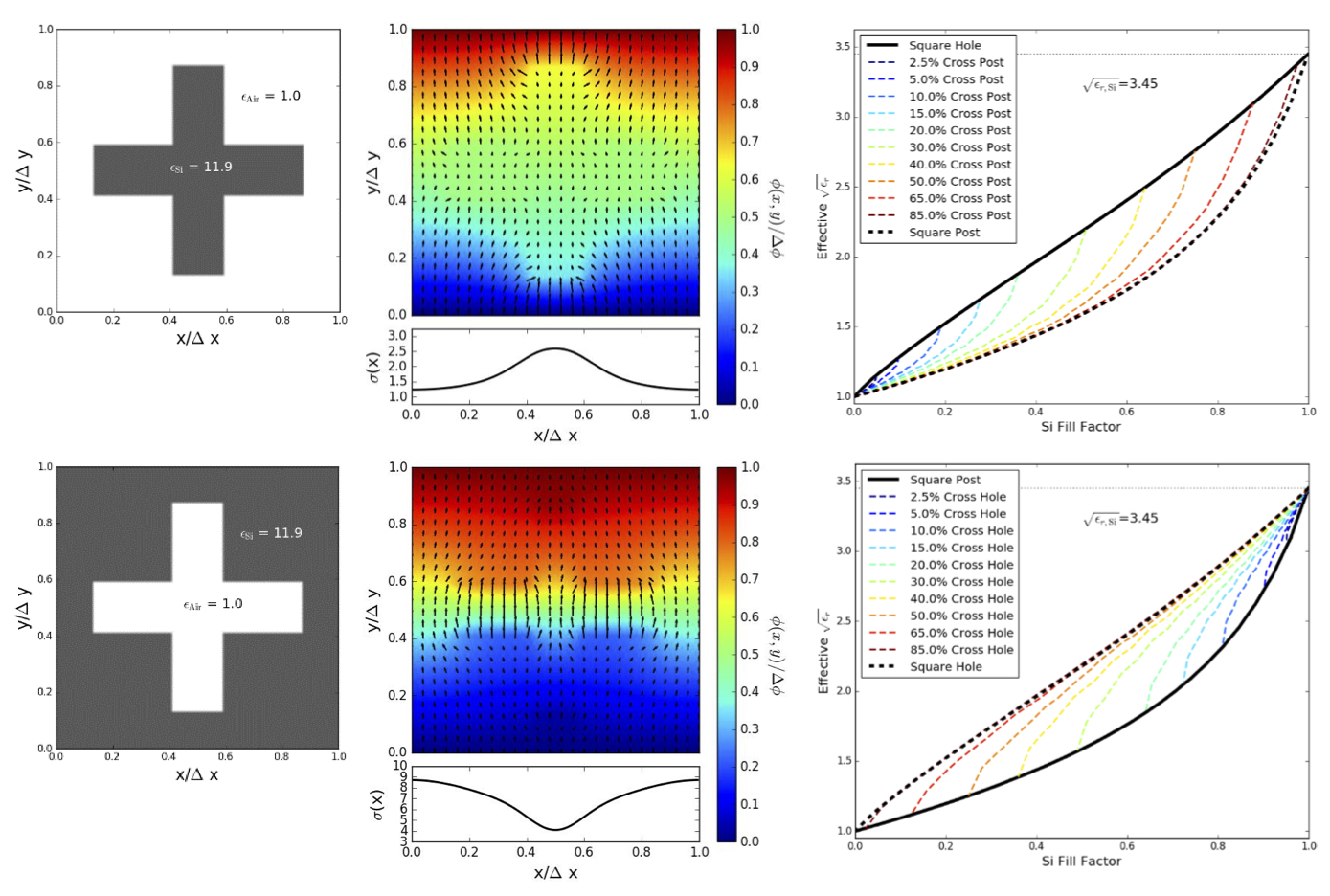
The process for calculating the effective dielectric constant for a cross pattern, both posts (upper) and holes (lower), consisting of air and silicon. (Left) An example pattern unit cell with silicon in grey and air in white. (Middle) The electric potential and electric field vectors for the solution corresponding to the example cross on the left. (Right) The extracted effective refractive index is plotted for various aspect ratio crosses.
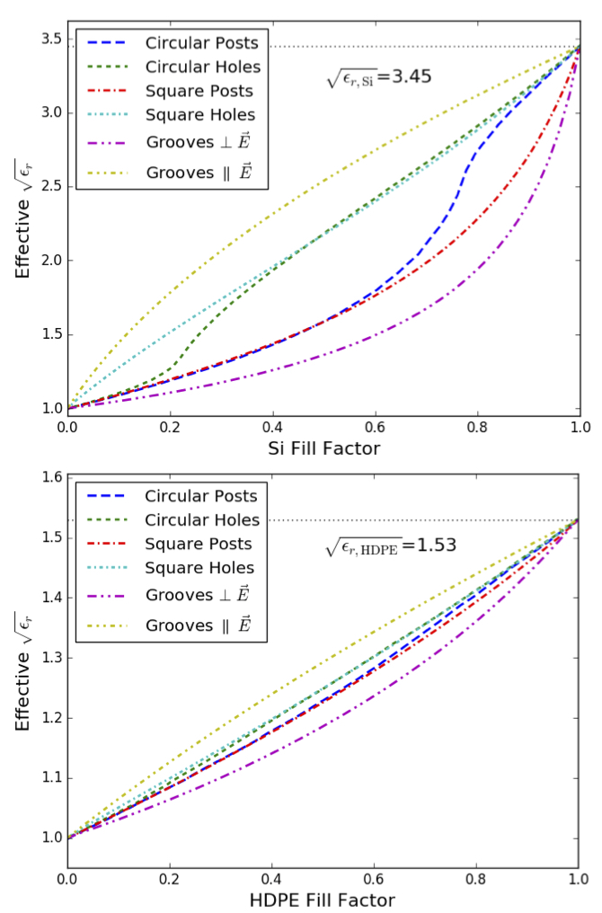
Plots of the effective index of refraction for different patterns in silicon (upper) and HDPE (lower). While the effective index is nearly linearly dependent on fill factor in HDPE regardless of pattern, a disparate behavior in patterns is found in silicon due to its much higher dielectric constant.
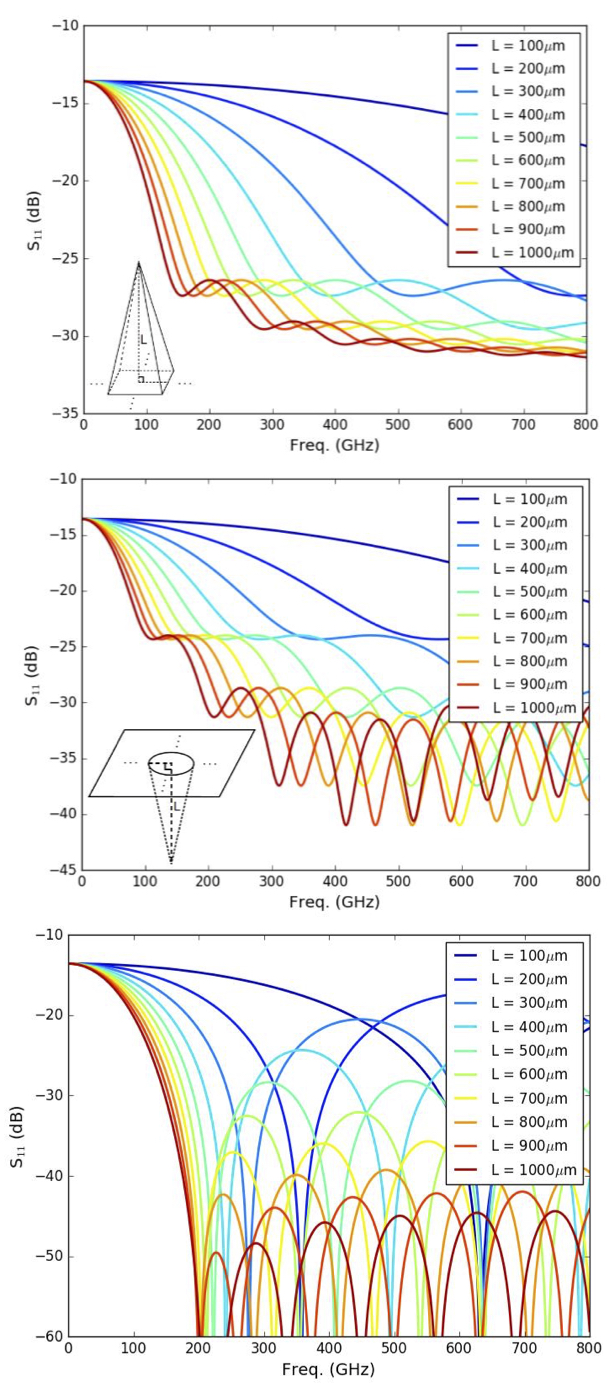
Plots of the return loss for tapered impedance transformers of various design with constant 100μm pitch. Square pyramidal tapers created by milling or sawing (top) have performance limited by the size of the tip of the tool, set to 6μm in this simulation, due to the finite mismatch between the end of the taper and the bulk. Drilled conical hole tapers (middle) are typically limited by the need to overlap drill holes to provide sufficient front side match to air due to the limited packing efficiency of circles. Using a table of effective dielectric constants as shown in the previous figure, one could create Klopfenstein tapered tools producing “optimal” impedance tapers (bottom).
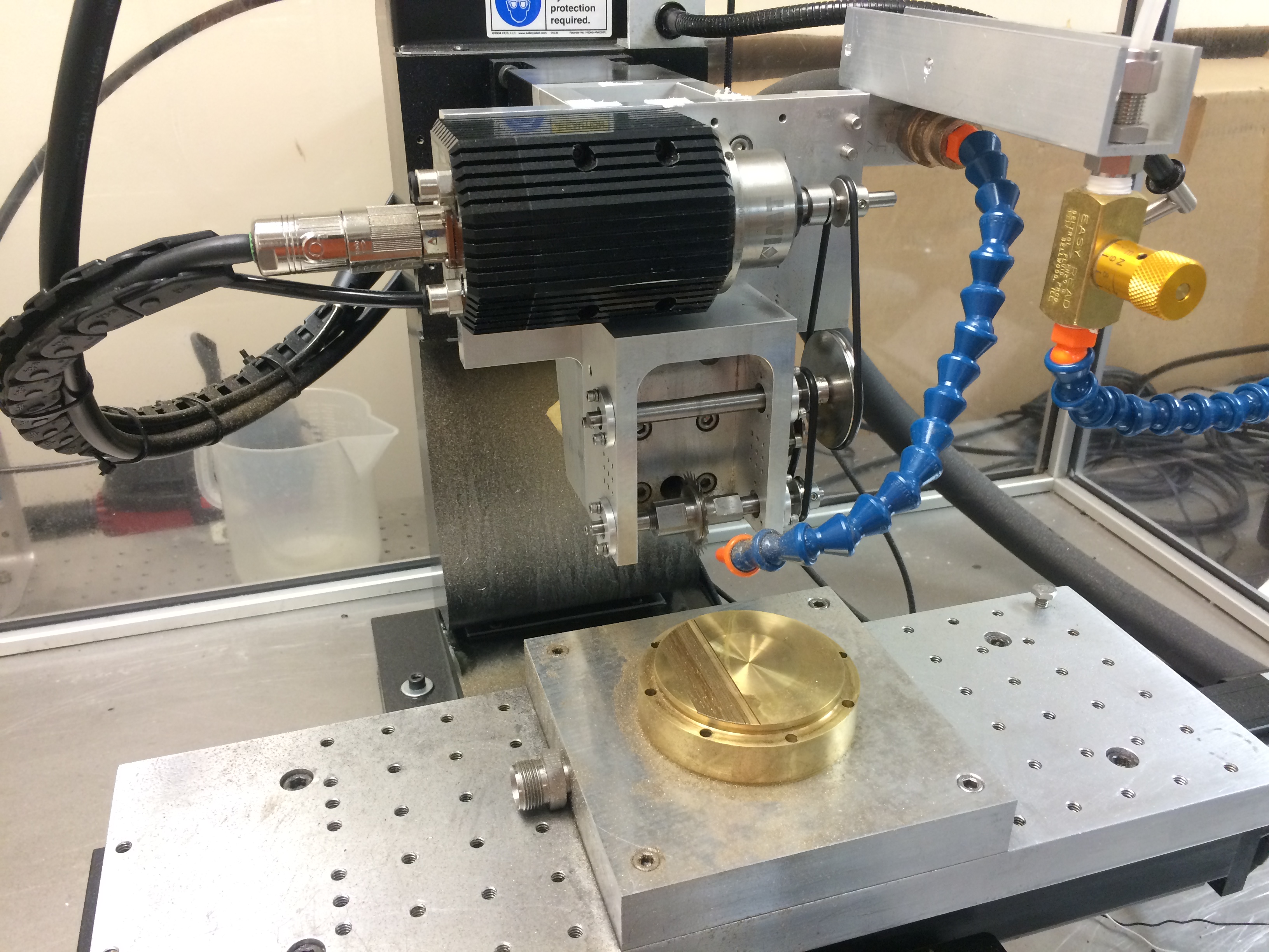
Slitting Saw jig attached to the receiver lab's micro-mill. We are currently attempting to cut 1mm deep V-grooves ona 250um pitch into brass to be used a a hot-stamping tool.
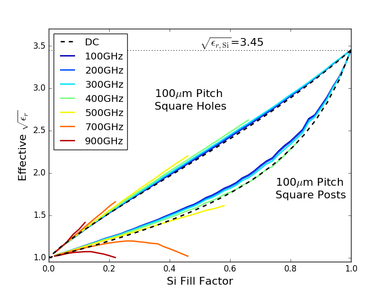
A plot of the frequency-dependent dielectric constant of square post and hole patterns in silicon on a 100um pitch. Frequencies for which the pitch is larger than a quarter to a third wavelength do not have well defined effective dielectric constants. Shown in dotted black lines are the effective capacitance calculation.