The timing of most solar radio events, except for noise storms (type I bursts),
is connected with flare occurrence and evolution, some with the
impulsive phase ("type III" and "type V bursts") and others with the main
phase ("type II" and "type IV bursts"). Observed brightness temperatures are
quite high (10 -10
-10 K) and indicate a non-thermal origin.
Mechanisms invoked for the interpretation depend on the location
of the emitting region (synchrotron or electron cyclotron maser at low-medium
altitudes and frequency > 1-3 GHz, and plasma radiation at the
local plasma frequency and its harmonic higher up in the corona and
frequency < 1 GHz) (see e.g. Dulk, 1985).
"Type I radio bursts" (continuum and fast pulses superimposed lasting
approximately 1 s, also named "noise storms") can evolve in hours and days.
The probable origin of the phenomenon is
the reorganization of magnetic structures. The
radioemission is supposed to occur in denser
and persistent structures that
scatter the radiation and augment the apparent size of radio sources.
They are visible not only on the disk but also at the limb where they show a
very low circular polarization percentage, due to
a depolarizing mechanism such as a large-angle scattering (Wentzel,
Zlobec and Messerotti, 1986).
The time scale of "type II bursts" is of the order of 1 minute. Excited by
superalfvenic shocks, they are usually associated with coronal mass ejections
(CME) and visible also at the limb. The propagation of the
associated shock causes a slow drift in frequency of the emission as
the shock propagates upwards in the corona and the local plasma
frequency decreases with decreasing density.
"Type III bursts" are visible on the disk and at the limb and have a
characteristic time scale of 5 s. They are generated by a beam
instability that occurs when an electron beam with velocity 0.2-0.6 c interacts
with the coronal plasma (Messerotti and Karlicky, 1992). The beam-plasma
density ratio is of the order of 10
K) and indicate a non-thermal origin.
Mechanisms invoked for the interpretation depend on the location
of the emitting region (synchrotron or electron cyclotron maser at low-medium
altitudes and frequency > 1-3 GHz, and plasma radiation at the
local plasma frequency and its harmonic higher up in the corona and
frequency < 1 GHz) (see e.g. Dulk, 1985).
"Type I radio bursts" (continuum and fast pulses superimposed lasting
approximately 1 s, also named "noise storms") can evolve in hours and days.
The probable origin of the phenomenon is
the reorganization of magnetic structures. The
radioemission is supposed to occur in denser
and persistent structures that
scatter the radiation and augment the apparent size of radio sources.
They are visible not only on the disk but also at the limb where they show a
very low circular polarization percentage, due to
a depolarizing mechanism such as a large-angle scattering (Wentzel,
Zlobec and Messerotti, 1986).
The time scale of "type II bursts" is of the order of 1 minute. Excited by
superalfvenic shocks, they are usually associated with coronal mass ejections
(CME) and visible also at the limb. The propagation of the
associated shock causes a slow drift in frequency of the emission as
the shock propagates upwards in the corona and the local plasma
frequency decreases with decreasing density.
"Type III bursts" are visible on the disk and at the limb and have a
characteristic time scale of 5 s. They are generated by a beam
instability that occurs when an electron beam with velocity 0.2-0.6 c interacts
with the coronal plasma (Messerotti and Karlicky, 1992). The beam-plasma
density ratio is of the order of 10 -10
-10 . Hence the exciters are weak
beams, which propagate upwards at high speed and produce
radio emission drifting rapidly in frequency.
The morphological characteristics of "type IV bursts" are quite complex,
because many subclasses exist. Fine structures are observed, such as spikes
lasting less than 0.1-1 s and quasi-periodic pulsations with periods of the order
of 1 s, but the typical evolution time of the phenomenon is 1 hour. They
appear on the disk and at the limb as stationary or moving radio sources. The
spikes are associated to the energy release and particle acceleration in flares
(Guedel and Zlobec, 1991); pulsations are probably connected with MHD
processes that occur in flux tubes (Li, Messerotti
and Zlobec, 1987).
. Hence the exciters are weak
beams, which propagate upwards at high speed and produce
radio emission drifting rapidly in frequency.
The morphological characteristics of "type IV bursts" are quite complex,
because many subclasses exist. Fine structures are observed, such as spikes
lasting less than 0.1-1 s and quasi-periodic pulsations with periods of the order
of 1 s, but the typical evolution time of the phenomenon is 1 hour. They
appear on the disk and at the limb as stationary or moving radio sources. The
spikes are associated to the energy release and particle acceleration in flares
(Guedel and Zlobec, 1991); pulsations are probably connected with MHD
processes that occur in flux tubes (Li, Messerotti
and Zlobec, 1987).
Notwithstanding the well known timing for flare-associated radio events, no definite optical counterpart of radio events or indirect signature in the pre- or post-event phases has been found. Most of the theoretical models are not yet fully enough developed to specifically predict the relative timing. In fact, if one assumes that the plasma radiation mechanism is operating for the majority of radio events, suitable diagnostics should be able to provide information on the structure of the corona, the topology of magnetic fields (Vrsnak et al., 1987) and the plasma turbulence. Hence such diagnostics could include line profile changes due to magnetic field modifications, plasma turbulence (Heinzel, 1990) and non-thermal features caused by particle beams (Canfield and Chang, 1985). Such information would be of fundamental importance, as it is directly or indirectly related to the plasma processes that produce the radioemission. A common diagnostic could be the width of selected lines, if sufficiently sensitive to the local change of non-thermal motions associated with the radio event (propagation of the exciter) or with favorable conditions in the pre-event phase (higher turbulence level) or the post-event phase (lower turbulence level for decay or enhanced turbulence level as a by-product of secondary processes). It is very difficult to think of a diagnostic for weak beams which excite type III bursts, mainly because their very low density does not seem to produce any detectable effect if one assumes the estimates by R. Esser (1992).
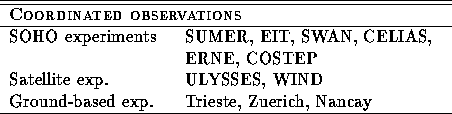
>From the above considerations, it is worthwhile to perform simultaneous coordinated observations from space with UVCS and other optical and particle SOHO instruments, ULYSSES and WIND and from ground-based solar radio instruments. It is important to analyze as many radio events as possible, classify them, and search for some signatures in the available lines, in particular increased line widths and changes in ionization state. The multichannel radiopolarimeter operated by the Trieste Astronomical Observatory for solar research is a suitable tool for resolving fast radio phenomena (average time resolution: 20 ms). As it does not provide spatial information, radioheliographic measurements are needed to complete the frame in the radio band. For this purpose the Nancay radioheliograph is an excellent European facility that could operate in coordinated observing campaigns; furthermore the frequency agile radiospectrograph operated by the ETH in Zuerich could provide the extended band coverage required for event interpretation.
Due to the complex zoo of solar radio phenomena no specific observation is proposed, but the suggested strategy is to operate the Trieste instrument as a ground-based support in as many coordinated observing projects as possible to have an extended data set of events analyzable in different bands and with different criteria but under a common frame. This is especially important as SOHO will be operating in a period of minimum solar activity, which means that flare-related events will be infrequent. This program will be closely tied to the CME and Shock Wave programs.
Optical Signatures Related to Solar Radio Events