|
 |
 |
|
 |
|
 |
|
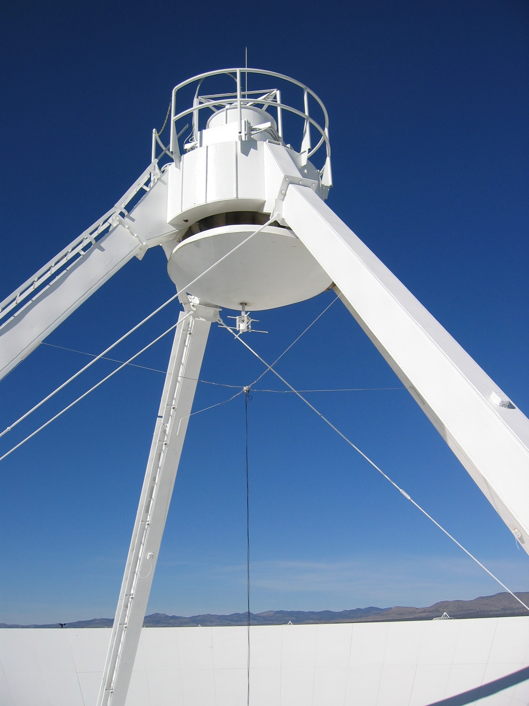
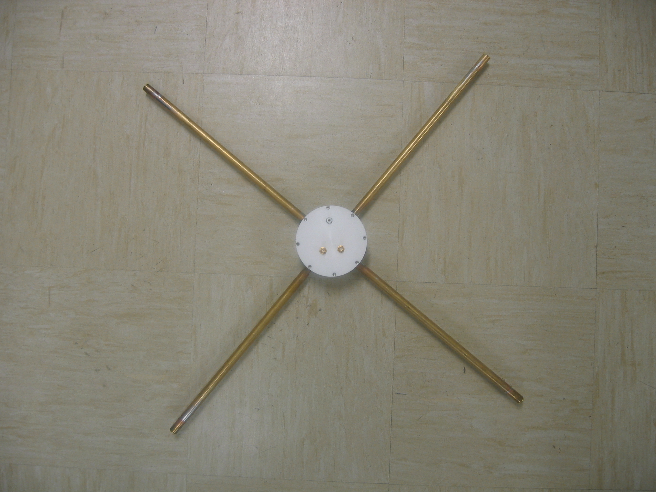
VLA long wavelength feeds:
4m, 1.5m, and 0.9m |
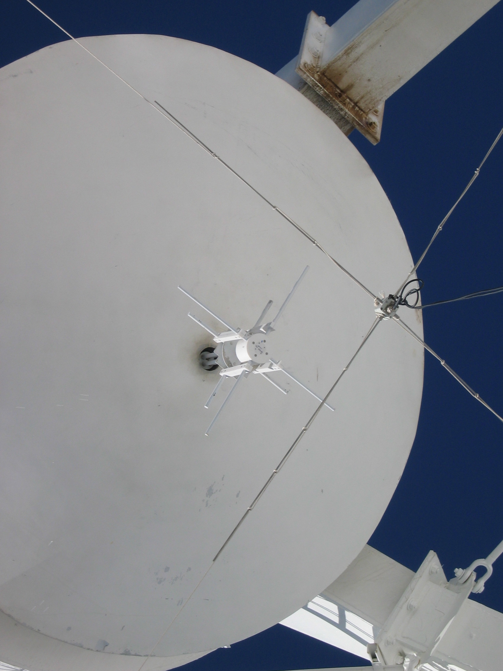
VLA long wavelength
feeds (close-up) |
VLA long and short
wavelength feed |
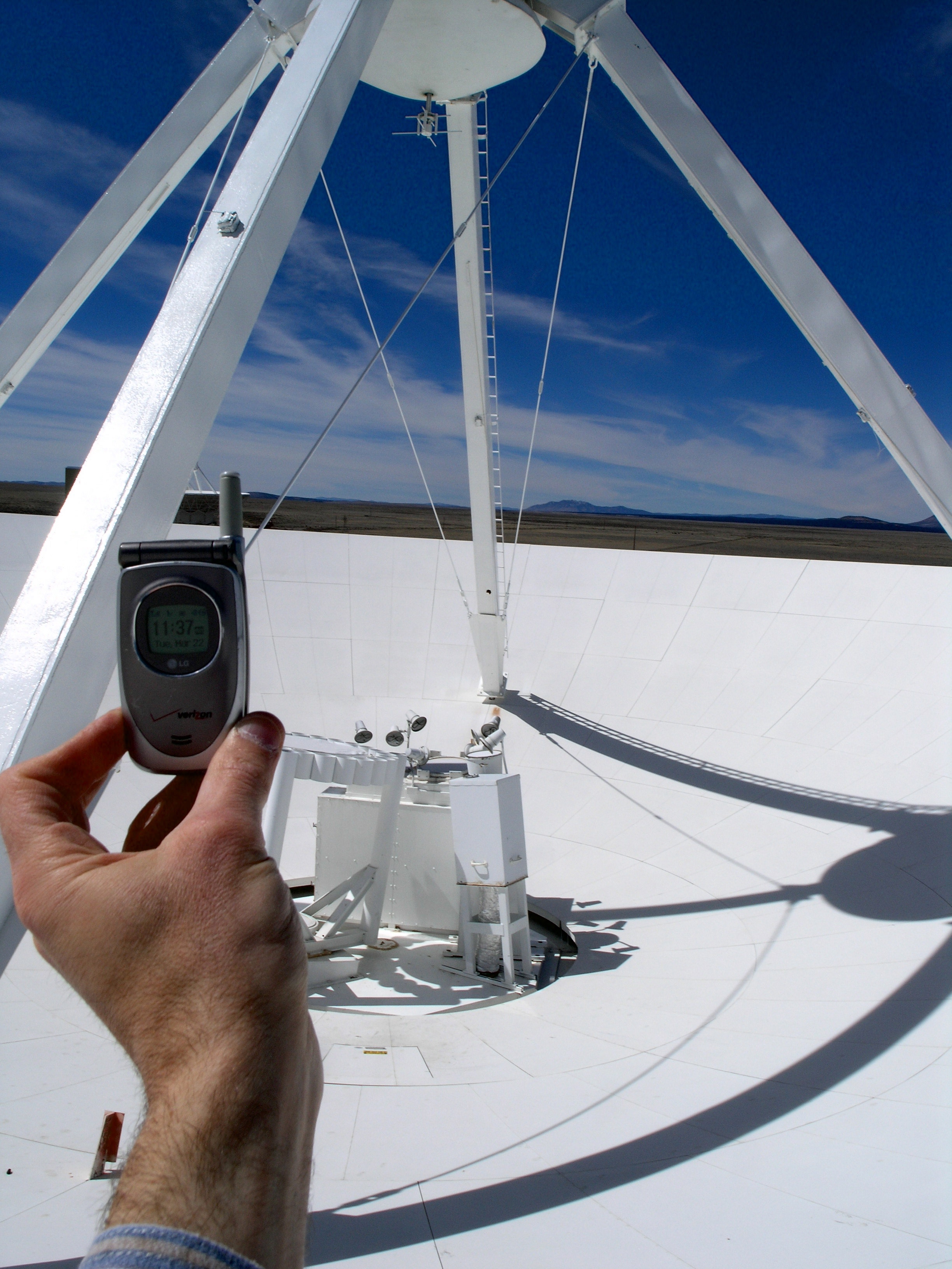
RFI at the VLA - 5 bars |
|
 |
|
 |
|
 |
|
 |
|
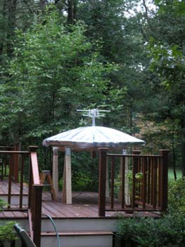
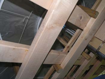
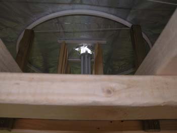
| Mockup of the inner 95% of a VLA sub-reflector with dipole feeds for 1.5m and P-band feed assemblies. Surface accuracy is ~2 inches (center to edge). |
Internal Structure of the mockup (1) |
Internal Structure of the mockup (2) |
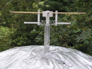
Close up of the mockup top surface and dipole assemblies |
|
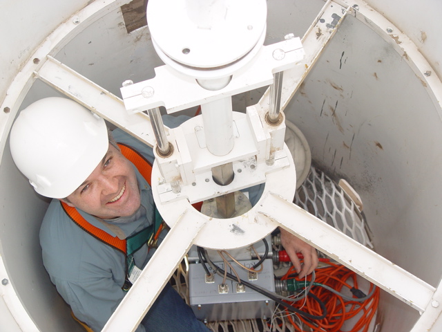
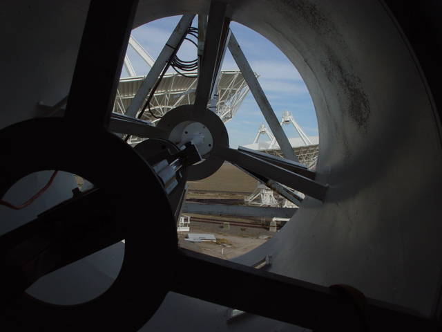
Prime Focus Barrel Cabin |
 |
|
 |
|
| Looking down into the barrel, showing 1.5m and P-band receiver boxes. |
Looking outward showing receiver support structures. |
|
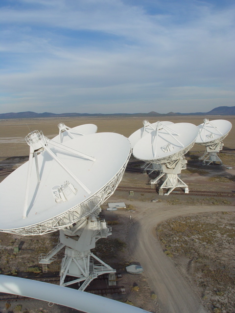
D-configuration |
 |
|
 |
|
Viewed from the apex of
antenna 8. |
Half of the
D - configuration from ground level. |
|
Feed Testing |
 |
|
 |
|
 |
|
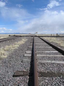
| Rails to Destiny |
Mounting the 1.5m feed on antenna 17. |
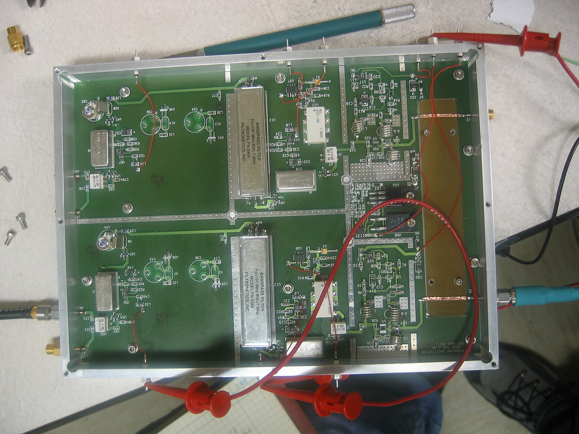
Test setup for total sky power measurement (call on/call off trace visible on screen). Narrow band front-end filters in foreground, near pipe (needed in testing to eliminate TV carriers). The 74 MHz receiver RF box nearest the camera. |
|
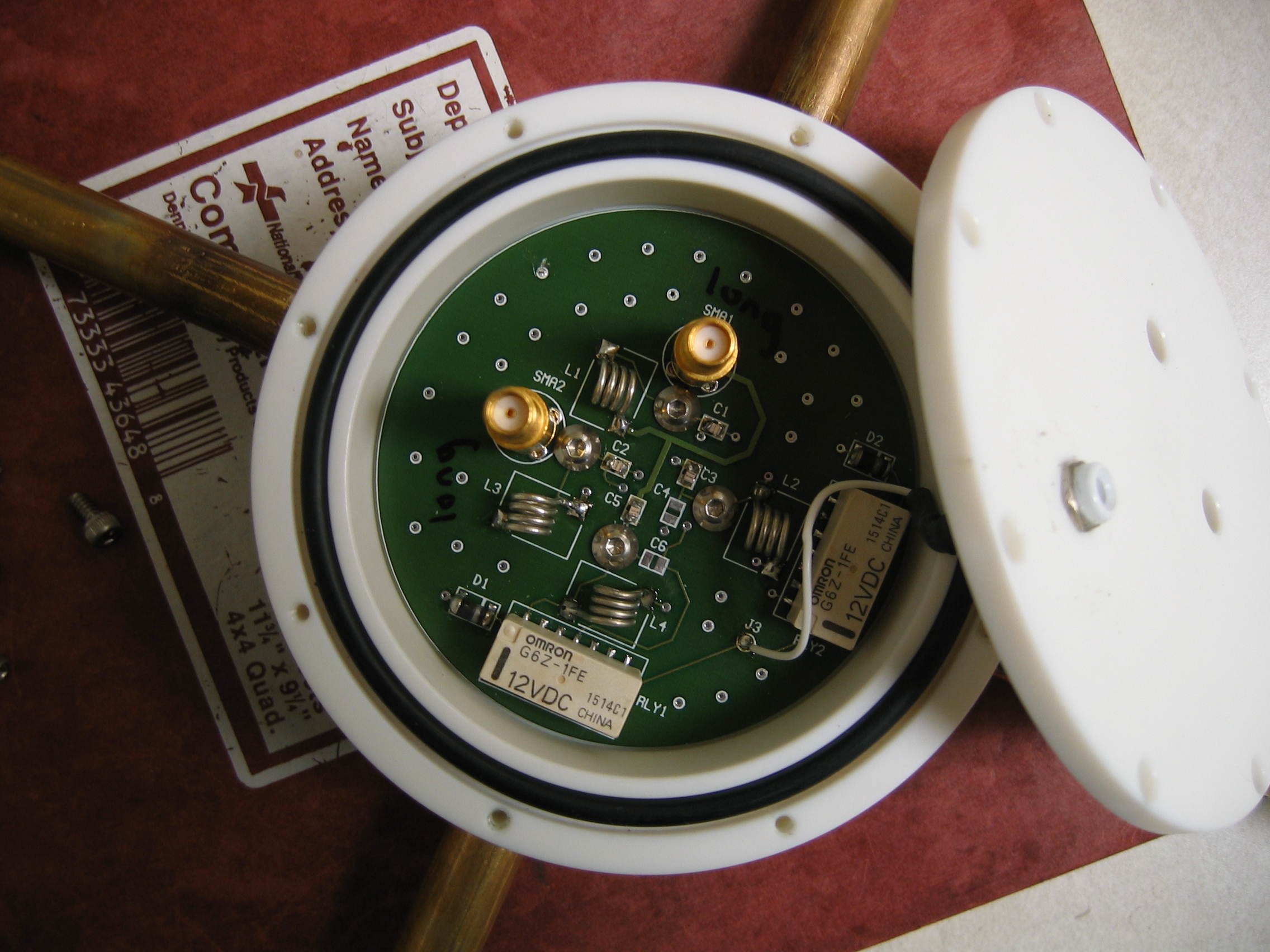
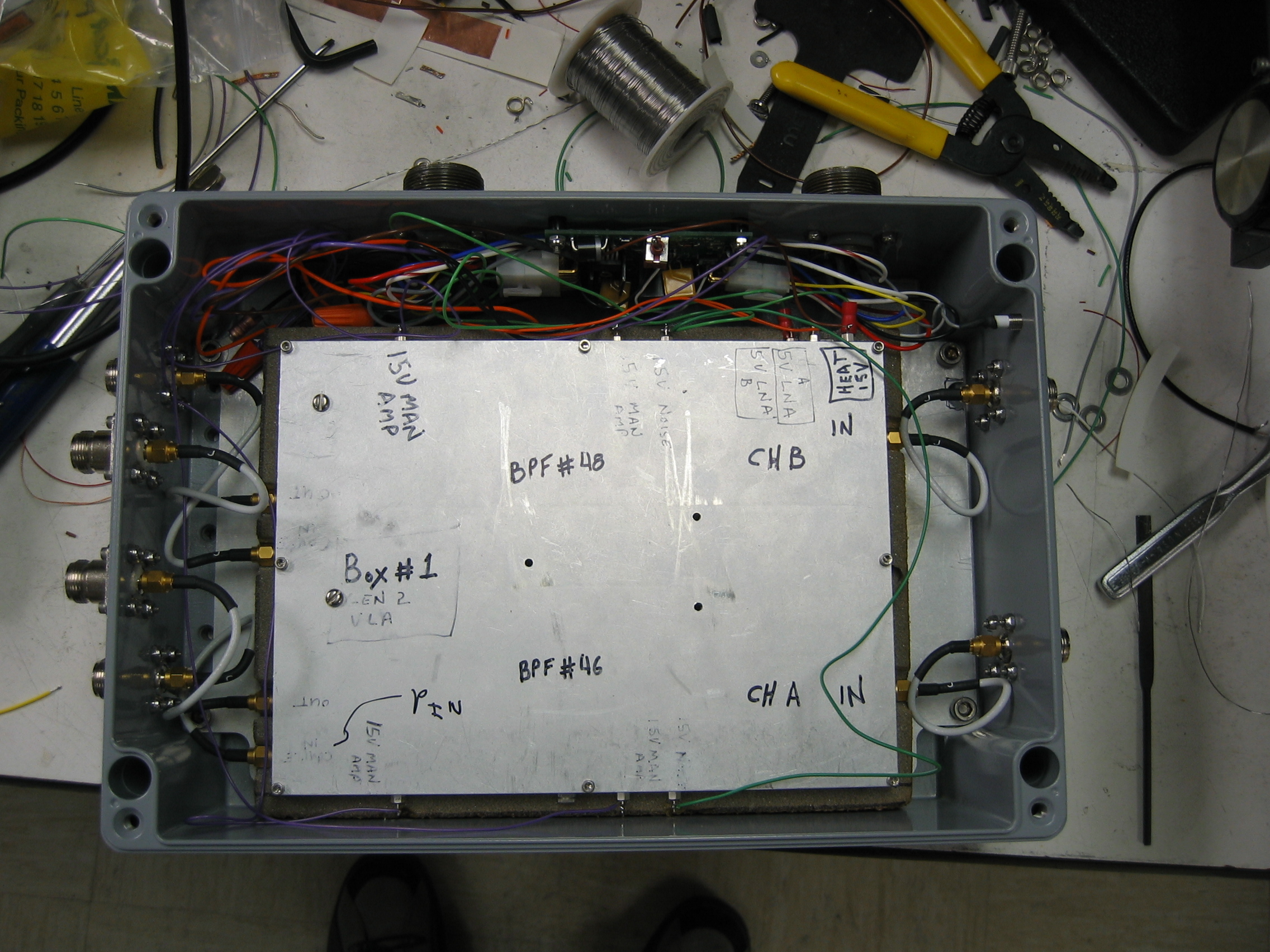
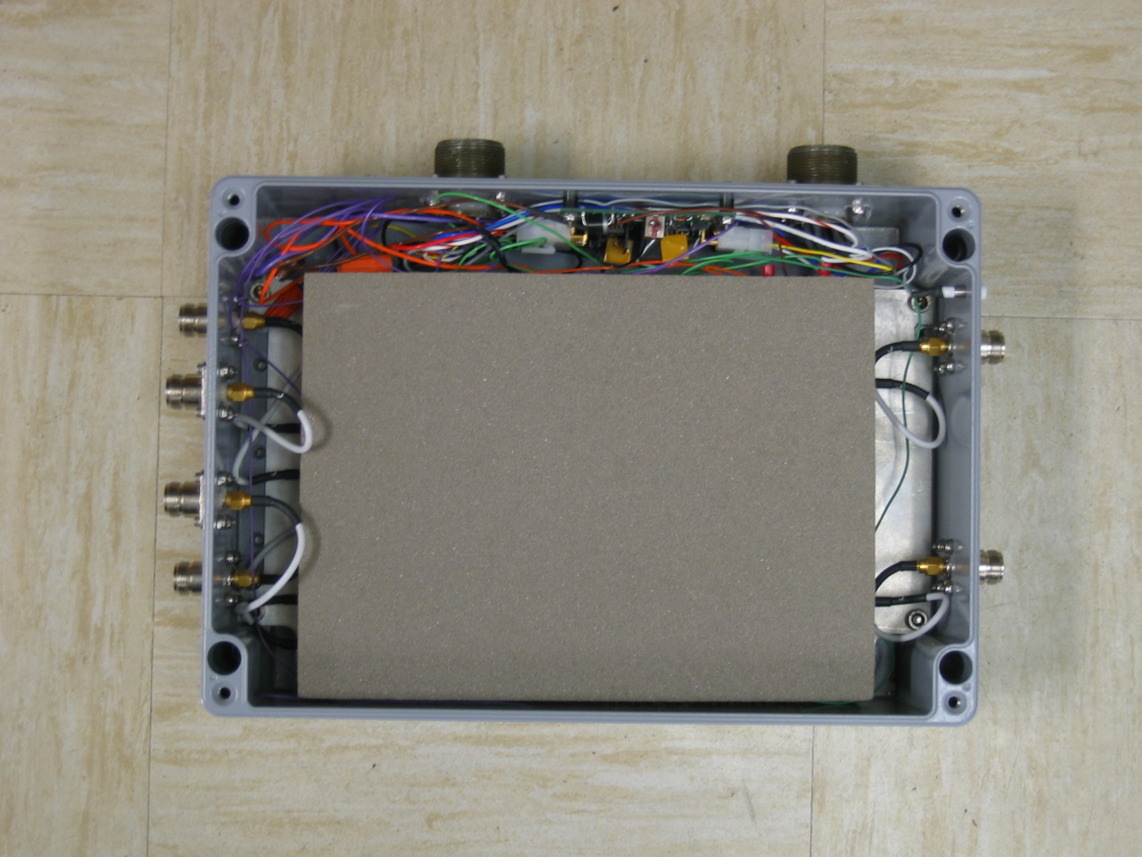
Production Receivers |
 |
|
 |
|
 |
|
 |
|
 |
|
| |
|
|
|
|
|