The SWAS Instrument -- A More Detailed Description
The SWAS instrument is comprised of seven major subsystems:
- (1) the signal detection subsystem consisting of two submillimeter heterodyne receivers built by Millitech Corporation
- (2) an acousto-optical spectrometer, provided by the University of Cologne in Germany
- (3) the telescope assembly
- (4) the star tracker assembly
- (5) the instrument control electronics
- (6) the instrument structure
- (7) the thermal control subsystem
Other than the receivers and the spectrometer, Ball Corporation
provided and integrated all subsystems and environmentally qualified the
instrument for launch and on-orbit operation.
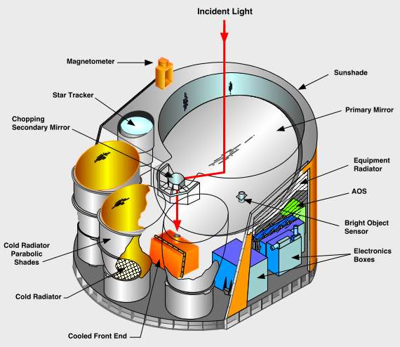
Since many of the objects to be studied by SWAS are shrouded from view
optically, pointing of the SWAS telescope is achieved by identifying and
tracking visible stars in the vicinity of the regions of interest. As SWAS
orbits the Earth, a star tracker is used to identify star fields and maintain
lock on these fields when SWAS is taking data.
Click to enlarge
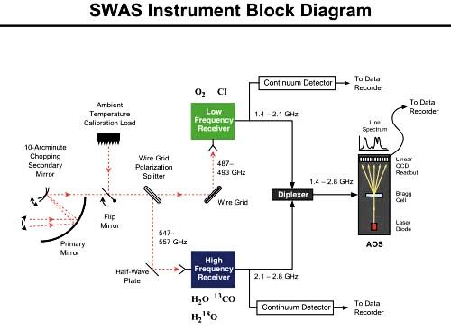
The principle by which the SWAS instrument operates is simple:
- Radiation collected by the 68 x 53 cm polished aluminum primary mirror is split in two with each half being brought to a focus within each of the two heterodyne receivers.
- These receivers, which are passively cooled to approximately 170 K to enhance their performance, and the following amplifier circuits select a radio frequency (RF) band within +/- 350 MHz (mega-hertz) of the incoming 550 GHz (giga-hertz) and 490 GHz astronomical radiation, down-convert the signals to the 1.4 to 2.8 GHz frequency range, and input them to the acousto-optical spectrometer.
- Inside of the acousto-optical spectrometer these RF signals are converted to acoustic waves within a crystal causing pressure waves to travel through the crystal. When illuminated by laser light, the alternating patterns of compression and expansion within the crystal acts like the finely spaced lines of a grating causing the laser light to be dispersed along one dimension with intensity variations along this direction that are proportional to the intensities
within the input 1.4 to 2.8 GHz band.
- The dispersed laser light is imaged onto a 1400-pixel charge-coupled device (CCD) line sensor with each pixel corresponding to 1 MHz of RF bandwidth, and the counts in each channel corresponding to the associated RF intensity.
- The linear CCD array collects the photoelectrons which are generated by the signal photons on the photodiodes of the CCD. The charges of each channel are read out every 10 milliseconds and are pre-integrated digitally for 2 seconds. These data, along with housekeeping data (temperatures, voltages, currents, etc.), are transferred to the spacecraft data storage system, resetting the counters in the linear CCD sensor, and then starts the process over again.
- Data are transmitted to NASA ground stations twice per day and, within 24 hours of its receipt at these ground stations, these data are received at the Smithsonian Astrophysical Observatory's SWAS Science Operations Center. The science content of the data is analyzed and new astronomical targets are selected for observation.
[Back]
|