Dynamic Effects of Elevation Counterweights
William N. Davis , SAO Central Engineering
January 7, 1999
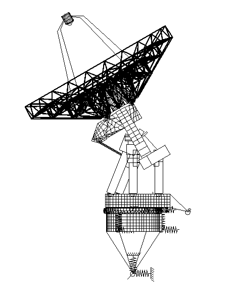
The SMA finite element model of a complete
antenna was updated to the current elevation counterweight design, and
balanced about the azimuth axis. Frequencies and modeshapes were calculated
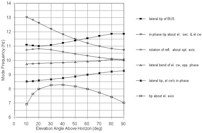
over the full range of elevation angle positions. The first mode, tipping
about the elevation axis, shows a frequency variation from 7hz at zenith,
to a maximum of 8.3hz at ~40o elevation, to 6.9hz at 10o
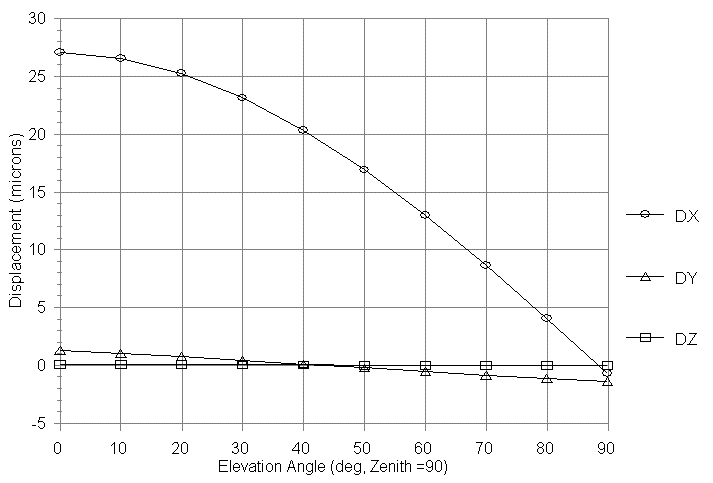
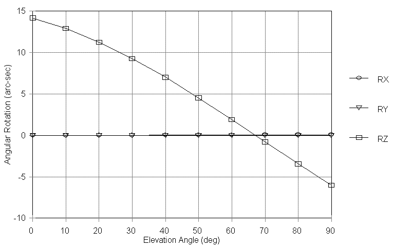
elevation. A static analysis was also performed to determine the motion
of mirror 3 as a function of elevation angle.
Discussion:
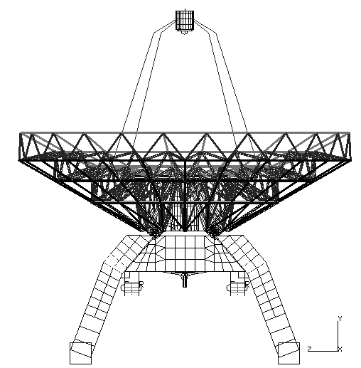
The SMA Antenna model is shown in Figure 1. The counterweighted reflector was modified to have a balanced weight of 23960 lbs. The mass distribution of the mount was modified to a balanced weight of 87874 lbs. This is about 7% less than the predicted balanced weight of 93349 lbs. by George Nystrom, however there are some design changes in progress on the cabin and environmental control unit which will affect the total mass and its distribution. Since the lower modes are primarily influenced by the reflector mass, elevation counterweights and the stiffness of the drivescrew, the results given here should not vary significantly with the mount mass or its distribution. We will update this model once the final cabin design is completed to verify this opinion. The reflector was rotated through elevation angles from 10o above horizon to zenith, and the first 6 mode frequencies are plotted as a function of elevation angle in Figure 2.

Conclusions:
The analysis results are documented here, and the impact on optical performance will be determined by other project personnel.