To appear in Proc. SPIE 3356, Infrared Astronomical Instrumentation, 1998, in press
The Infrared Array Camera (IRAC) for the Space Infrared Telescope Facility (SIRTF)
G. G. Fazioa, J. L. Horaa, S. P. Willnera, J. R. Stauffera, M. L. N. Ashbya, Z. Wanga, E. V. Tollestrupa, J. Pipherb, W. Forrestb, C. McCreightc, S. H. Moseleyd, W. F. Hoffmanne, P. Eisenhardtf, E. L. Wrightg
aHarvard-Smithsonian Center for Astrophysics, 60 Garden Street, Cambridge, MA 02138-1516
bUniversity of Rochester, Rochester, NY 14627
cNASA/Ames Research Center, Moffett Field, CA 94035
dNASA/Goddard Space Flight Center, Greenbelt, MD 20771
eSteward Observatory, University of Arizona, Tucson, AZ 85721
fJet Propulsion Laboratory, California Inst. Of Technology, 4800 Oak Grove Dr., Pasadena, CA 91109
gUniversity of California at Los Angeles, Los Angeles, CA
The Space Infrared Telescope Facility (SIRTF) contains three focal plane instruments, one of which is the Infrared Array Camera (IRAC). IRAC is a four-channel camera that provides simultaneous 5.12 x 5.12 arcmin images at 3.6, 4.5, 5.8, and 8 microns. The pixel size is 1.2 arcsec in all bands. Two adjacent fields of view in the SIRTF focal plane are viewed by the four channels in pairs (3.6 and 5.8 microns; 4.5 and 8.0 microns). All four detector arrays in the camera are 256 x 256 pixels in size, with the two short wavelength channels using InSb and the two longer wavelength channels using Si:As IBC detectors. The IRAC sensitivities (5 sigma, 200 sec) at 3.6, 4.5, 5.8, and 8.0 microns are 6, 7, 36, and 54 microJanskys, respectively. Two of the most important scientific objectives of IRAC will be to carry out surveys to study galaxy formation and evolution during the early stage of the Universe, and to search for brown dwarfs and superplanets.
The IRAC instrument will address the four major scientific objectives defining the SIRTF mission1,2. These objectives are (1) to study the early universe, (2) to search for and study brown dwarfs and superplanets, (3) to study ultraluminous galaxies and active galactic nuclei, and (4) to discover and study protoplanetary and planetary debris disks. The sensitivity requirements for IRAC were specified in terms of these science goals, and are given in Table 1, which gives the point-source sensitivity in each band.
Table 1 - IRAC Top-level Sensitivity Requirements
|
Channel No. |
Center Wavelength (microns) |
Total Bandwidth (%) |
Broadband Sensitivity (microJy) (5s , 200 s) |
|
1 |
3.6 |
20 |
6 |
|
2 |
4.5 |
23 |
7 |
|
3 |
5.8 |
25 |
36 |
|
4 |
8.0 |
38 |
54 |
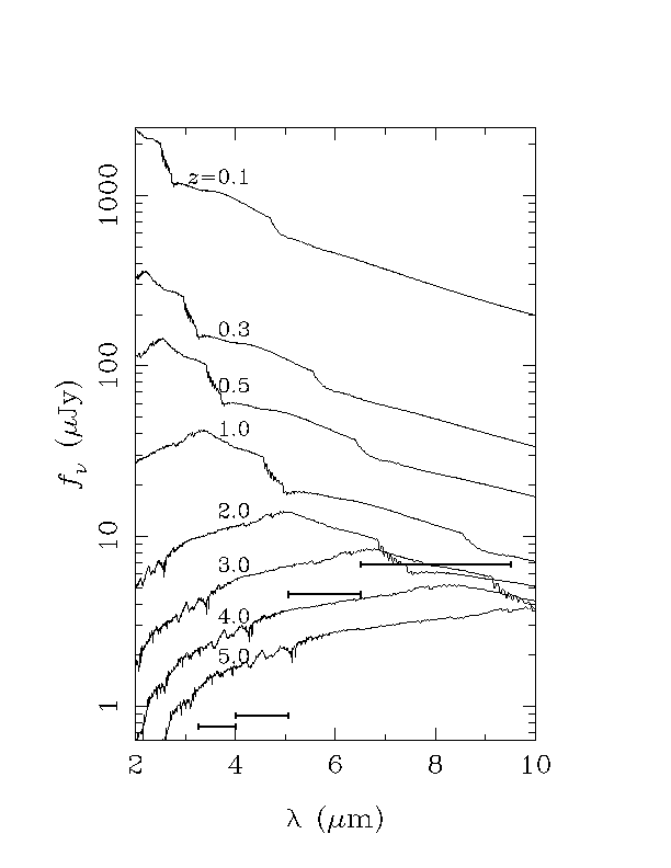
To carry out the studies of the early Universe, IRAC would perform deep near-infrared surveys to detect normal galaxies to redshift (z) to z equal to or greater than 4. Although UV-bright z = 3 galaxies have now been detected via the "UV-dropout" technique3, IRAC will sample the rest-frame near-IR spectral region of normal galaxies at high redshift. Sufficient numbers of these galaxies will be detected to construct the luminosity function at different redshifts, permitting discrimination between density evolution, luminosity evolution, or a combination of the two. This IRAC project requires that these normal galaxies be observed to a redshift of three, where the quasar space density is a maximum. At this lookback time, we know that at least one extragalactic population, quasars, has undergone significant evolution, and we may expect to see significant evolution in normal galaxies. The IRAC investigation will determine the number counts of normal galaxies as a function of redshift by using four- color imaging (3.6, 4.5, 5.8, and 8.0 microns) and photometric redshift determination. In a deep survey of 0.2 square degrees, approximately 600 galaxies with z equal to or greater than 3 and 1500 galaxies with z equal to or greater than 2 and with a luminosity L> L* will be detected. In Figure 1 we show spectra generated using the GISSEL96 version of Bruzual-Charlot models4, along with the IRAC sensitivities (1s , 500 seconds).
Figure 1 - Model spectra as a function of redshift (z) for a maximally old L* galaxy in which all stars formed in an instantaneous burst at z = infinity, and evolve passively thereafter, in an HO = 50, qO = 0.1 cosmology. The flux is normalized to an absolute K magnitude of -25.1 today5. Also shown are the IRAC sensitivities (1 sigma in 500 sec).
During the past two years, ground-based surveys have begun to succeed in detecting large numbers of relatively young, relatively nearby brown dwarfs in star-forming regions, young open clusters and the field. IRAC will be able to extend those efforts to older and lower mass brown dwarfs and superplanets. In nearby star-forming regions like Taurus, IRAC should be able to detect isolated objects down to near the mass of Jupiter. In the nearest and best-studied open clusters - in particular, the Pleiades and the Hyades - IRAC should be able to detect brown dwarfs down to 0.01 solar masses (selected based on their IRAC colors; see Figure 2). If the mass function below the substellar limit estimated for the Pleiades from ground-based studies is valid for the field, a survey of a few hundred square degrees of the sky should detect a population of brown dwarfs that are older (to a few Gyr) and lower mass than are likely to be found from ground-based surveys such as 2MASS or DENIS.
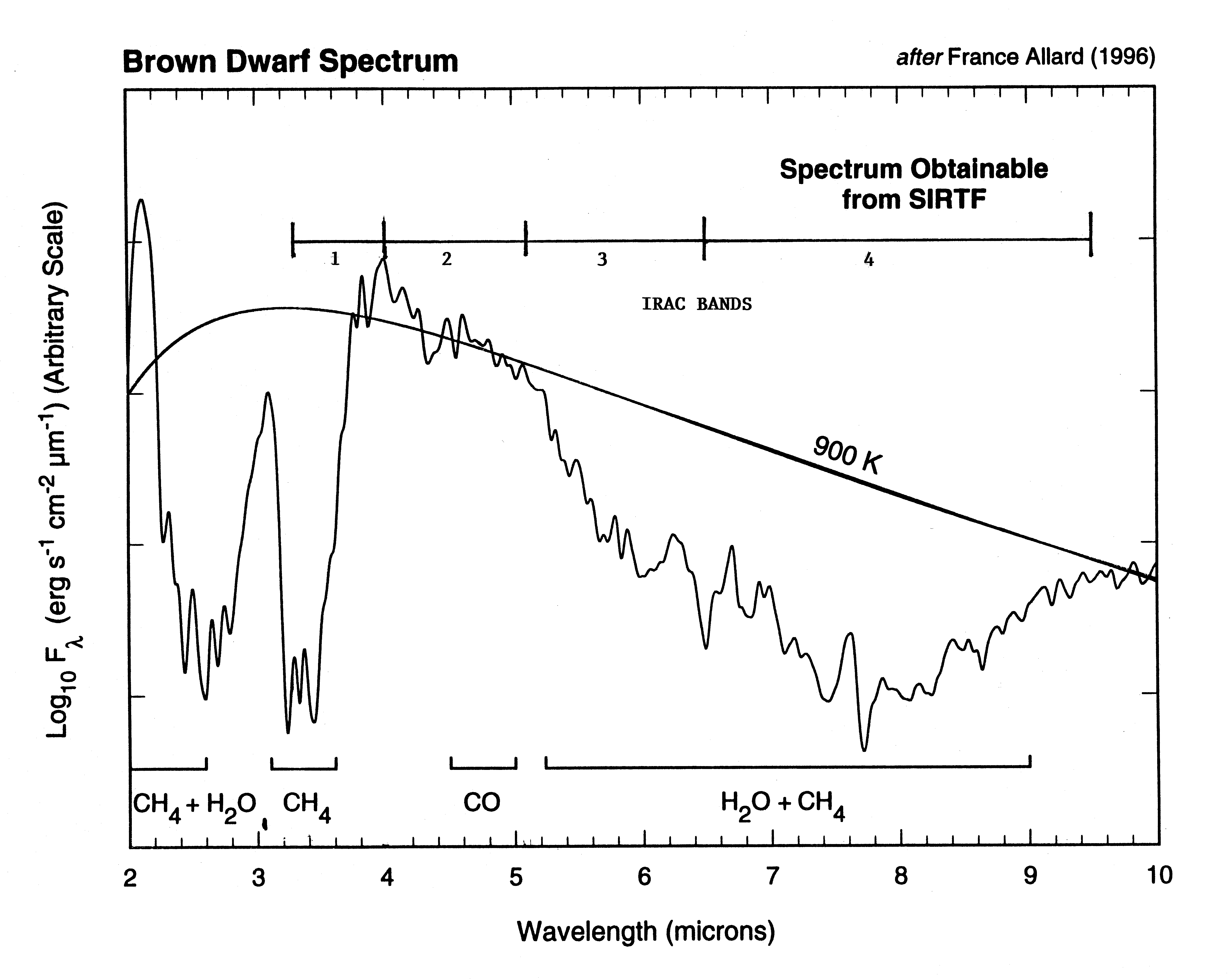
Figure 2 - The IRAC bands are shown in relation to a model brown dwarf spectrum and a 900K blackbody.
Active Galactic Nuclei (AGNs), which include quasars, radio galaxies, and Seyfert galaxies, generate tremendous amounts of energy in very compact regions, by processes that are not completely understood. An Ultraluminous Infrared Galaxy (ULIRG) is a galaxy with a 8-1000 micron luminosity LFIR >5 x 10¹¹ Lsun . These objects are gas-rich and harbor ongoing star formation, and are more likely than their lower-luminosity counterparts to contain AGNs. These objects often exhibit morphological peculiarities indicative of interacting or merging systems. IRAC imaging of individual galaxies will be used to investigate the link between ULIRGs and quasars, to examine quasar host galaxies, and to image the nuclear structure in nearby IR-luminous galaxies. IRAC will provide the highest resolution imaging capability for objects identified with SIRTF or other space-based surveys (e.g., WIRE), and will enable the study of the various emission components, such as the compact core and disk, and identify companion galaxies in interacting systems. A deep survey for quasars with z equal to or greater than 4 will also be performed. These objects are difficult to observe in optical surveys, but IRAC will be sensitive to objects out to z = 5-20. Assuming the same volume density as has been previously determined for the 4.2 < z < 4.7 range, a survey covering 60 deg2 should find about 50 quasars in the 5 < z < 10 and 10 < z < 20 redshift ranges, if they exist.
The goals of the study of protoplanetary and planetary debris disks are to 1) characterize the properties of potentially planet-forming disks associated with young stars, 2) study the character of planetary debris disks around mature, solar-type stars, and 3) compare the origin, composition, and properties of extra-solar debris disks with those of the various dust components of our solar system. The presence of planetary debris systems was detected by IRAS in many nearby main-sequence stars (with Vega, Fomalhaut, and Beta Pictoris being the prototypical systems). These disks consist of swarms of 1-100 micron particles in the zone approximately 50-200 AU from the star, and are confined mostly to the stellar equatorial plane. The surface brightness of these disks is low and requires a cryogenic telescope that can perform the sensitive far-IR photometry necessary to detect the IR-excess that is the signature of these systems. Observations with ISO have added more candidate systems. IRAC will be used to survey star-forming regions, open clusters with a range of ages up to a few hundred Myr, and field stars to detect such disks, determine their frequency, and place constraints on the timescales in which these disks clear and the timescale for the formation of planets.
Finally, IRAC is a general-purpose camera that can be used for imaging and surveys in a wide variety of other investigations. The four-band imaging of the IRAC instrument will produce a database that can be important for many different observational programs. These very sensitive large-area surveys will be a significant legacy of this program and an important astronomical resource far into the future.
IRAC views simultaneously two nearly adjacent 5.12 x 5.12 arcmin fields of view (FOVs) near the center of the SIRTF focal plane. A pickoff mirror reflects the light into the camera housing. Each of these fields are split into two channels by a dichroic beamsplitter, with the 3.6 and 5.8 micron channels in one FOV and the 4.5 and 8.0 micron channels in the other. The optical layout for two of the channels is shown in Figure 3. Each FOV has a lens doublet that reimages the SIRTF focal plane (located near the pickoff mirrors) onto the detector arrays at a scale of 1.2 arcsec/pixel in each band. The beamsplitters reflect the short wavelength and transmit the long wavelength bands, and a Lyot stop is placed at the pupil to eliminate stray light. A fixed filter is placed in front of each detector to define the bandpass. The image quality in the current optical design meets the wavefront error goal of <0.05 waves rms over each FOV and in all wavelengths in the bandpasses in all channels. The filter bandpasses were optimized to carry out the mission science objectives described above, as well as to provide maximum sensitivity in each band. In particular, comparing the flux detected in the 3.6 and 4.5 micron bands will be a good discriminator in searches for brown dwarfs, and the 5.8 and 8.0 micron bands were optimized to achieve the highest sensitivity for the deep galaxy surveys6.
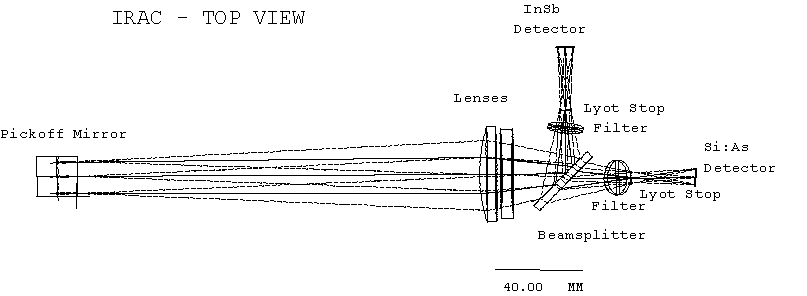
Figure 3 - IRAC optical layout, top view. A second pair of optics and focal planes are below this set in the lower section of the optical housing.
The IRAC mechanical layout is shown in Figure 4. The IRAC camera housing is machined from a single aluminum piece. The incoming beam passes through the outer section walls that act as baffles, and enter the inner chamber where the optics are located. There is a chamber on the top and bottom for each of the two FOVs. All optical components are mounted on a single aluminum block, the optical housing, shown in Figure 5. The beam enters the front of the housing through the doublet, and is either reflected off the beamsplitter (mounted at a 45deg angle in the center of the block) and exits through one side through the Lyot stop and filter onto the InSb array, or passes though the beamsplitter, Lyot stop, and filter to exit out the back side of the housing and onto the Si:As array. The arrays are mounted on thermally-isolated stages that can be controlled to the appropriate temperature for each array type.
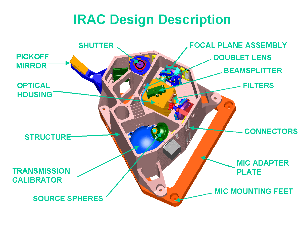
Figure 4 - IRAC mechanical design. Two of the four focal planes are shown, the other two are in a similar compartment on the underside of the structure. Not shown is the light-tight cover that attaches to the top surface.
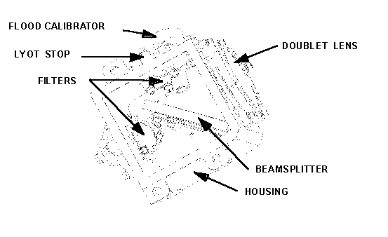
Figure 5 - The IRAC optical housing, shown from the underside (the mounting surface).
There are two sets of internal calibration sources in IRAC. One set consists of flood calibrator sources located near the detectors that can directly illuminate the array independent of the camera optics. Figure 5 shows the location of two of the four flood calibrator units, mounted near each array on the optical housing. There is also an integrating sphere that can be illuminated by two different sources. The sphere and one of the sources can be seen in Figure 4. The only moving part in IRAC is a shutter located near the entrance aperture of the camera. The rear of the shutter blade contains a reflective surface which, when the shutter is closed, allows light from a transmission calibration source to enter the instrument optics. With the transmission calibrator off, the closed shutter also serves as a dark slide, blocking all radiation from entering the camera.
The detector arrays used by IRAC are manufactured by Raytheon's Santa Barbara Research Center (SBRC). The 3.6 and 4.5 micron channels use 256 x 256 pixel InSb detectors7,8, and the 5.8 and 8.0 micron channels use 256 x 256 pixel Si:As Impurity-Band Conduction (IBC) devices9,10. The detector characteristics and performance requirements are summarized in Table 2. The performance numbers listed are the ones necessary to reach the sensitivity requirements that are listed in Table 1, given the total IRAC system throughput and performance of the telescope and optics.
Table 2 - Summary of IRAC Array characteristics and requirements
|
Parameter |
InSb detector arrays |
Si:As detector arrays |
|
Format |
256 x 256 pixels |
256 x 256 pixels |
|
Pixel size |
30 micron |
30 micron |
|
Well size (minimum) |
105 e- |
105 e- |
|
Quantum Efficiency (mean) |
>80% @ 3.6 and 4.5 microns |
>23% @ 6.3 microns |
|
Read Noise (mean) |
<10 e- |
<20 e- |
|
Dark Current (maximum) |
< 1 e-/s |
< 10 e-/s |
|
Operability |
99.5% |
99.5% |
|
Electrical pixel-pixel crosstalk (maximum) |
5% |
5% |
|
Operating power (maximum) |
1 mW |
1mW |
|
Operating temperature |
13 - 17 K |
4 - 7 K |
|
Radiometric stability (1 sigma rms) in 12 hr |
1.0% |
1.0% |
|
Radiation Susceptibility to 70 MeV Protons, - Single 100 Rad exposure, pre-anneal - 100 Rad total exposure and post- anneal - After 800 Rad total exposure and post-anneal |
Operability:
>90%
>99%
>95% |
Operability:
>90%
>99%
>95% |
The warm front-end electronics are divided into timing/driving and analog electronics. Operation of the detector is handled by the timing/driving electronics, which provides bias and clocked voltages to the arrays and controls the frame readout rate. The analog electronics convert detector output from analog to digital format. To isolate digital noise from the analog signal path, the analog circuitry will be built on separate boards from the timing/driving circuitry, and will also be physically separated into its own compartment within the electronics box. Sequential clocking of the detectors can be accomplished with gate-array technology to achieve the required data throughput rate. Programmable Digital-to-Analog Converters (DACs) provide adjustable voltage levels for bias and clocked signals.
The electronics will use multiple (Fowler) sampling to reduce the effective read noise (see Figure 6). After the reset, a number N of initial frames are coadded in the IRAC frame buffer. The minimum sample time for each complete readout of the full array is 0.2 seconds. After an exposure time has elapsed, a second set of N samples are obtained and the two sets of samples are differenced before transferring the data to the spacecraft. All four channels will operate in parallel and simultaneously image the two FOVs in the four IRAC bands.
In addition to the full-frame mode, there is a subarray mode in which a 32 x 32 pixel region is read out at a faster rate (minimum readout time of 10 msec). This mode is primarily for observing bright sources that would otherwise saturate the array even at the shortest full-array readout times, or for observing time-critical events where a finer time resolution is required.
IRAC has four operational modes: Off, Observe, Calibrate, and Diagnostic. In the Off state, no power is dissipated in the cold assembly and all the electronics are off. Only one instrument can be on at any time on SIRTF, so IRAC will be off when the other instruments are in use. The Observe mode is used for normal data taking (see below). In calibration mode, the shutter can be closed and the calibration sources operated. In both Observe and Calibrate modes, various operational parameters such as temperature, bias voltages, and Fowler number can be set. Several test functions are available in Diagnostic mode, including the ability to transmit test patterns to evaluate the DSPs and transfer electronics. An annealing function will also be available to temporarily raise the temperature of the detectors if necessary to reduce dark current after large solar flares.
IRAC has one basic observing function - "step and integrate". This means that the telescope will move and settle at a new position, and then the camera will take one or more images in all four channels. Several of these operations can be combined to map out regions larger than the IRAC FOV. This observing function can be done in either full- or sub-array mode, and there will be a number of selectable parameters such as integration times and number of images at each position. The observer will specify the observation by filling out an Astronomical Observation Template (AOT) form with the desired parameter values. The observer will have the capability on the AOT form to choose mapping parameters such as map field size, mapping step size, dither pattern, orientation, etc. and will provide a flexible means of specifying a proposed observation. The scheduling of the observation will depend on the visibility of the field, given the pointing constraints of SIRTF. The visibility of a field is a function of its ecliptic latitude, with the highest visibility being at the ecliptic poles which are in a continuously viewable zone. However, all parts of the sky will be visible at least twice per year.
The SIRTF mission and the science instruments have held their preliminary design reviews in the last half of 1997, and the critical design reviews will be held in the summer to fall of 1998. The detailed IRAC design is now being finalized in preparation for these design reviews. SIRTF is currently scheduled to launch in December 2001, and to begin science observations in early 2002.